Honeywell Pir Sensor Wiring Diagram

Unique Wiring Diagram For A Honeywell Thermostat Honeywell Thermostats Diagram Thermostat Installation

Unique Wiring Diagram For A Honeywell Thermostat Light Switch Wiring Thermostat Wiring Ceiling Fan Switch

Honeywell Motion Sensor Wiring Diagram Diagram Base Website Wiring Diagram Sequencediagram Inadda It

Lovely Y Plan Wiring Diagram Combi Boiler Diagrams Digramssample Diagramimages Thermostat Wiring Underfloor Heating Systems Heating Thermostat

Multipirandlamp Circuit Light Switch Wiring Sensor Switch
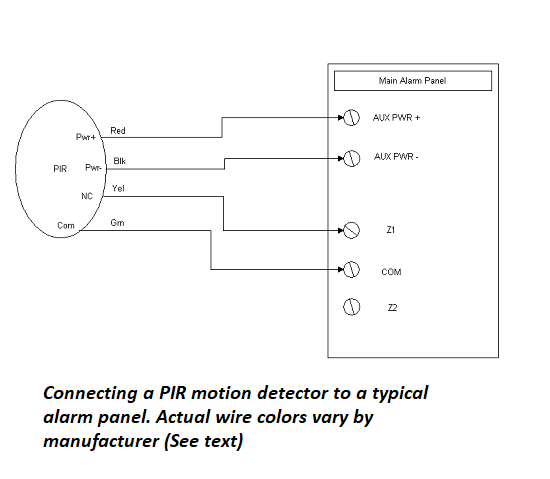
Motion Detector Wiring
Two wires will connect the alarm system s auxiliary power supply to the terminals labeled 12v on the is216.
Honeywell pir sensor wiring diagram.

Motion Sensor Wiring Diagram Electrikals Sensor Motion Sensor Map

Pin On Electronics Projects
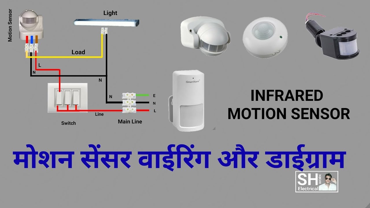
How To Install Pir Motion Sensor Connection Diagram Youtube

How To Wire Pir Sensor Light Youtube Light Sensor Light Switch Wiring Motion Sensor Lights
Source : pinterest.com
